
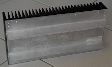
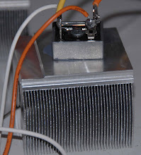
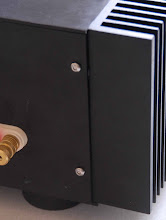
And I saw this beautiful heatsink from Conrad Engineering while I was searching for heatsinks in the internet.
This is my second Nelson Pass project...the first one was the Ono Phono amplifier.
So here I am, building this F4 amplifier...it is still being built.
Conrad Engineering is in Melbourne, Australia..
I happened to be in Melbourne (July, 2007) and I ordered 4 pcs of this heatsink which was promptly delivered to the hotel I was staying.
Then there were the reviews by 6moons.....which confirmed my project was the right one.
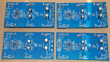
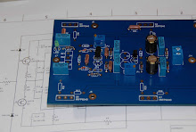
My friend in Hong Kong designed the PCBs and supplied the matched jfets and Power Fets and some components.


I then started to source the other components locally. I also have to decide whether I should spend more money on 'audiophile' components or not. In the end, I had to buy some 'specific' resistors and capacitors from the US and Taiwan.
I also had to find someone to 'tap' the holes in my heatsinks to mount the FETs and also the 'L-shape' bars to fix up my case.
I also could not find anyone to help me make the aluminium case, so my friend in Hong Kong offered to make it in Shenzhen.
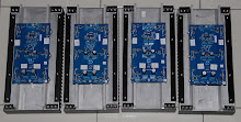
Here are the four heatsinks.
I had to tap some 96 holes and that made me realised that it is not really worth the trouble and cost to make a case in Singapore..better to buy ready made case from China, Thailand or Taiwan. That would be a better choice....
By the way, making a 'made-to-measure' case is also very expensive.
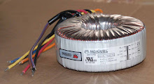
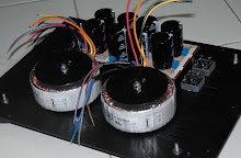
Now....about the Power Suppliy.....
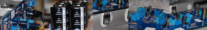
The PSU E-caps......35V 22,000uf each
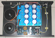
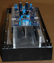
This is my make-shift power supply...and test bench...

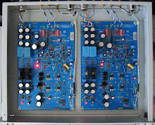
other PCBs that have been 'tested' ....now waiting for the cases...
I finally found some 'feet' for the case.
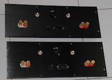
The cases came on 25th Sep. I started fixing the components to the rear panel. I then fixed the 'feet' for the bottom plae.

Next to fix were the L-shape bars on the heatsinks. I finally fixed all the 4 heatsinks.


They all fitted perfectly. My friend's drawing were perfect. The 'tapping' were also accurate.
I put some heatsink compound between these L-shape bars and the heatsinks, hoping that they will help to dissipate some heat away from the heatsink to the rest of the case.
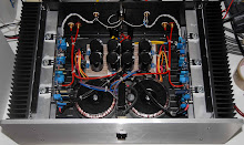
 I then arranged the E-caps, trans and the bridge rectifiers to see how it looks with them on the bottom panel.

Still short of connecting the input cables and speaker cables, I hook up the amplifier to see how hot it will get. I finally set it to 1.1 Amp..and 'run' the amplifier for more than 20 hours. I also wanted to adjust the DC off-set, and see how much it drifts over the period.
so far so good.....will try to connect the input cables and speaker cables,,,,,

 Some of you would have noticed that I swapped around the Speaker terminals and RCA sockets. My friend said that usually the 'Red' side is on the left of the Rear panel if you are looking at it from the back.
Since my pre-amp only accepts 'Balanced' inputs, I have to use my F4 amps in Bridge mode, so I fixed a 'Balance-input' socket
I also got more power in this configuration to drive my Response 2.5 speakers.
I next 'run' in the amps further to further check the DC offset in 'bridged mode', i.e. between the 2 '+' speaker terminal.....also taking every opportunity to 'run-in' the amp. I have some blackgate capacitors and was told that they take 100 hours to burn-in.....hmmmm
Now with the Top cover on...back view....perfect fit.....very happy with the design...


Now from the front...isn't it pretty ?...very nice looking for a diy set.
Now all wired-up and ready to 'sing'.....


Now connected to the left channel....ready to 'sing' the first song...
the other channel....


3 comments:
sk nice blog it look good it looks better then mine you know
Very nice and patient work and please advise your result. Thanks.
Post a Comment